

Crampr Dampr
2019-2020, Senior Design

Crampr Dampr is a wearable device that eases menstrual pain. This was a two-semester long capstone design project completed as part of my bachelor's degree in mechanical engineering. Crampr Dampr won the Couloucoundis Award for Best Senior Design Presentation (2020) awarded by the Mechanical Engineering Department of the University of Pennsylvania.
While I was involved with every portion of the product development, my main focus was the massage system, subsystem interfaces and CAD. The approach we took to developing the product and a breakdown of its subsystems are detailed below.
Problem Definition and Background
Dysmenorrhea, more commonly known as period pain, is caused by the contractions of the uterus during menstruation. 84% of people who menstruate are afflicted with this and 1 in 10 experience pain so severe they cannot carry out daily activities. With a problem so widespread and complex, no one solution works for everyone. Cost, inaccessibility, inconvenience and preexisting medical conditions prevent many existing pain relief methods from being a universal solution.
Initial research included interviews with gynaecologists, experts in menstrual pain relief, and peers afflicted with the problem, alongside an in-depth literature review of studies conducted in the field. In addition, we released a survey (with over 100 respondents) to explore the state of menstrual pain relief with a larger sample size. An example of the kind of feedback we received can be seen in the pie chart on the right.
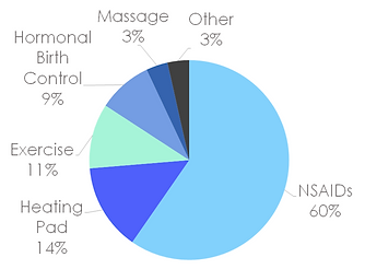
Figure: What do people use to treat their period pain?
Heat and massage, two proven therapies for pain relief, are ancient methods that had not found their way into modern life. We found the reason lay in the inconvenience associated with going for a massage appointment or the discomfort of carrying around a bulky heating pad. Crampr Dampr uses these topical methods while remaining comfortable, discreet and convenient.
The design of the product focussed on the main systems - Massage and Heat, but also considered secondary systems such as - Materials, Power, Controls, User Interface and Safety
Massage System
Before the development could begin, we needed to define desired system characteristics or massage parameters relevant to pain relief. Due to a lack of quantitative information available regarding menstrual massage, the team held a data collection event that was attended by 40 women. At the event, attendees were interviewed for demographic and personalised information. They were provided with mockups mimicking various massage methods and asked to detail their reaction to each one. Finally, they were asked to massage themselves with the help of a force gauge that would allow us to determine the forces associated with massage and its desired location. Some of the important results are pictured below. In addition we found that a dynamic massage, with an alternating, rolling or oscillatory component was more desirable, as opposed to a compression-band-like mechanism.

Figure: What is a comfortable massage force?

Figure: Where is menstrual pain felt?
As pictured on the right, a series of possible designs were investigated through analysis and even preliminary prototyping. This highlighted the benefits of an inflation based system over a more mechanically driven one. Further down-selection led us to choose a system with sequentially inflating air bladders controlled with the help of solenoid valves and an air pump.
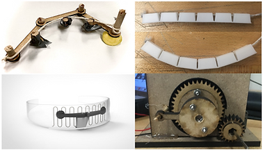
Figure: Early Mechanical prototypes

Figure: Effect of Bladder Dimensions on Perceived Force
Air bladders chosen were of a rectangular pillow shape and made of TPU. This was determined by - ease of manufacturability, tolerance to heat, structural integrity and ability to withstand required air pressures.
In order to determine the size and number of bladders, the relevant constraints were: a) when inflated, the bladders needed to protrude into the body deep enough to reach target forces and b) there needed to be a sufficient number of bladders to achieve a 'dynamic' effect. As shown on the left, the desired force was modelled as a function of the bladder dimensions.
In order to ensure that the bladder would push into the body without protruding outwards, they were designed such that the outer surface of the bladder was made stiffer to prevent it from ballooning. More importantly, the air bladders were held by a band that can be tightened independently of the rest of the system. This band configuration was modelled as a series of springs as shown below (left) and allowed us to choose a material that had a stiffness more than that of the average abdomen. This ensures that protrusion away from the body is minimised and the displacement is directed inwards. While this was initially done using fat and muscles thicknesses of an average woman, the model was adapted to reflect the effect of the setup on a range of body types as shown below (right)

Figure: Simplified Non-Rigid Model
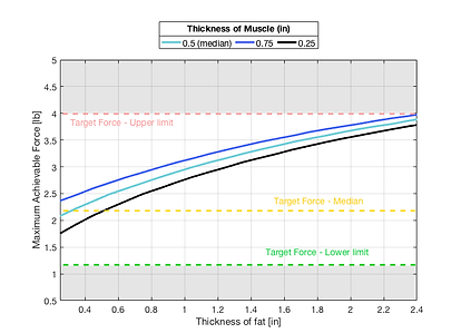
Figure: Perceived Force For Varying Body Types
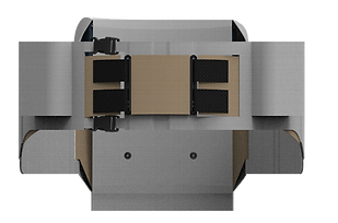
Relevant air pressure values could be extracted from the models. Based on these, as well as power requirement and size, an air pump and solenoid valves could be chosen. A CAD render of the final system form is pictured below.
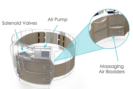
Figure: CAD Render of Final Massage System
Heat System
Based on research, we were able to find the skin temperature required for effective pain relief. The goal was to use strategically placed heating wires to meet this temperature while minimising power consumption. A finite element model was constructed using COMSOL Multiphysics to determine the heat flow from the wires through various layers of the device. As shown below, this was used to determine the desired nichrome wire temperature.

Figure: COMSOL Model with Final Wire Selection
The target areas of heating were restricted to the mid/lower abdomen regions. To cover this area with a single length of wire, we would have to either exceed the recommended voltage difference for a wearable, or the device would consume far too much power. Thus, we had to determine the thickness of the wire, and the number of sections it would need to be divided into. Based on Ohms Law, Joule heating, and nichrome resistance parameters, we developed a model to predict what wire configuration would let us achieve the desired temperature with the least amount of power. The results shown on the right allowed us to select the wire.

Figure: Model for Heating Wire Selection
A range of wires were also physically tested to validate the model. In addition, since we had only modelled steady state behaviour, the experiments allowed us to predict the time it would take to reach steady state. Ultimately, the device heats up in under 2 minutes. A CAD render of the final heat system is pictured below

Figure: Final Heat System CAD
Secondary Systems
Power
Power consumption of the various systems of the device was the biggest factor that affected design. For it to be portable, discreet and comfortable, we could not have the user lug around a huge battery pack. The power consumed by each component at maximum usage was calculated by extracting and using data from the systems modelled above. All components were designed to run at the same voltage, rated safe for a wearable device. Most importantly, we were able to select a battery pack that could power the device for 5 hours with continuous usage. Power drawn by every system was experimentally verified and shown to corroborate the expected device endurance. The picture on the right depicts a setup to determine pump power consumption when it is inflating an air bladder that is experiencing an external force (corresponding to the reaction force of the body).

Figure: Power Testing Experimental Setup Example
Materials
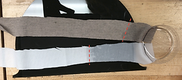
Figure: Capillary Action Material Test
The device is enveloped in a moisture wicking, fire resistant fabric to ensure maximum safety and comfort. Due to the presence of heating wires and the fact that the device is worn under clothing meant that getting rid of sweat build up was important to its design. The fabric had to maximise transport of water (or sweat) through to the other side of the band. Based on previous studies, the team devised experiments to test the effectiveness of a moisture wicking fabric. A capillary action test, to measure the water spread of a given material is pictured on the left.
Controls and User Interface
The device is controlled by a Bluetooth enabled remote control that can be slipped into a pocket or clipped onto a belt. The user can choose between three levels of massage intensity and toggle either system on or off independently of the other. The team also built a mockup of a mobile phone app that has the same functionality as the remote, but can also check the battery level and track the users cycle. Further stakeholder outreach is needed to choose between the two options.


Figure: CAD Render of Remote Control
Figure: App Mockup
Safety
The device is equipped with a temperature sensor that actuates a circuit breaker in case the wires overheat, the lithium ion batteries are built with a battery management system and based on the low voltage, the shock rating is imperceptible and causes no harm. In addition, the device has a quick release zipper, in case the user needs to quickly remove the device. The team has also prepared a self body check to ensure the effect of the massage is as expected and there are no extenuating issues.
Product Architecture
At its thickest section, the device is 1.25" thick which meets our pre-defined 1.5" maximum thickness. As shown in the picture below (left), the device is not visible under everyday clothes. The velcro adjustments and fastenings are designed such that the device fits the 25th-75th percentile US woman. All components selected perform well, even under the heated conditions that would be experienced by the device, and with average usage the batteries are expected to operate safely without requiring replacement for over 5 years.

Figure: Mockup of the Device Worn Under Everyday Clothes

Figure: First Fit Prototype with Fully Functional Heat System

While we were unable to assemble the integrated system due to the university COVID-19 closure, each system was independently modelled and tested. CAD renders of the full system, as well as its fit on a mannequin are pictured below.

Figure: Crampr Dampr Fitted on a Mannequin
Figure: Final Design CAD Render
Other Team Members: Folatomi Alli-Balogun, Vlasta Schutzenhofer, Abi Szabo, Audrey Walsh, Xinyue Wei